Arietta ALS436SS Instruction Manual Page 6
- Page / 24
- Table of contents
- BOOKMARKS
- LIB0102593 1
- English page 2 1
- Español página 12 1
- IMPORTANT SAFETY INSTRUCTIONS 2
- Tools and Parts 3
- Electrical Requirements 4
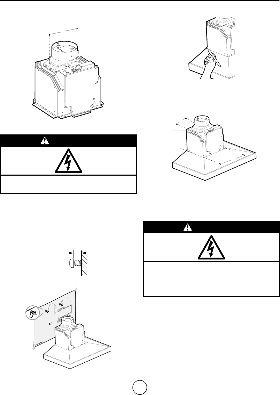
- Installation Instructions 5
- Electrical Connection 6
- Description of the hood 8
- Range Hood Care 9
- Replacing the halogen lamp 10
- WARRANTY 11
- APROBADO PARA APARATOS 12
- DE USO DOMÉSTICO 12
- SÓLO PARA USO DOMÉSTICO 12
- Lista de Materiales 13
- Requisitos eléctricos 14
- Instrucciones para la 15
- Conexión Eléctrica 16
- Descripción de 18
- Limpieza y cuidado de 19
- Limpieza 20
- Supercies de la campana 20
- Kit Recirculante Opcional 20
- GARANTÍA 21
Related products and manuals for Cooker hoods Arietta ALS436SS

 (2 pages)
 (44 pages)
© 2020, manymanuals.com. All rights reserved. | 0.283 s |
 Manymanuals.com
 Manymanuals.de
 Manymanuals.fr
 Manymanuals.it
 Manymanuals.pl
 Manymanuals.cz
 Manymanuals.es
 Manymanuals-pt.com
Comments to this Manuals